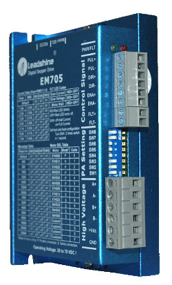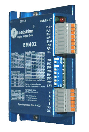

EM402 - Advanced Digital Stepper Drive with Stall Detection; Max 40 VDC / 4.2A
รายละเอียดสินค้า EM402 - Advanced Digital Stepper Drive with Stall Detection; Max 40 VDC / 4.2A
Features
-
Sensorless stall detection
-
Extra-low motor noise offers excellent quietness
- User password protection prevents others from copying your drive configurations
-
Optimizes torque and nulls mid-range instability
- Self-test and Auto-configuration technology
- Options to set output current and microstep resolutions via DIP switch or software
- Microstep from 1 to 512
- Supply voltage up to +40 VDC
- Output current programmable, from 0.3 A to 2.2A
- Automatic idle-current reduction and reduction rate is software configurable
-
Fault out prevents damages to your machines or the materials
- Step & direction control

Electrical Specifications
| Parameter |
Min |
Typical |
Max |
Unit |
|
Input Voltage |
20 |
24 |
40 |
VDC |
|
Pulse Input Frequency |
0 |
- |
50 |
kHz |
|
Logic Signal Current |
7 |
10 |
16 |
mA |
|
Isolation Resistance |
500 |
- |
- |
MΩ |
Operating Environment
|
Cooling |
Natural Cooling or Forced cooling |
|
|
Operating Environment |
Environment |
Avoid dust, oil fog and corrosive gases |
|
Storage Temperature |
-20℃ - 65℃ (-4 ℉- 149 ℉) |
|
|
Ambient Temperature |
0℃ -50℃(32℉ -122 ℉) |
|
|
Humidity |
40%RH -90%RH |
|
|
Operating Temperature (Heat Sink) |
70℃(158 ℉) Max |
|
|
Vibration |
10-55Hz, 0.15mm/s |
|
|
Storage Temperature |
-20℃ -65℃(-4℉ -149℉) |
|
|
Weight |
107 g (3.77 oz) |
|
The EM402 has two connectors, connector for control signals connections, and connector for power and motor connections.
|
Control Signal Connector |
|||
|
Pin |
Name |
I/O |
Description |
|
1 |
PUL+ |
I |
Pulse signal: This input represents pulse signal, each rising or falling edge active (software configurable, see EM drives software operational manual for more detail); 4-5V when PUL-HIGH, 0-0.5V when PUL-LOW. For reliable response, pulse width should be longer than 10μs. Series connect resistors for current-limiting when +12V or +24V used. The same as DIR and ENA signal. |
|
2 |
PUL- |
I |
|
|
3 |
DIR+ |
I |
Direction Signal: This signal has low/high voltage levels, representing two directions of motor rotation.For reliable motion response, DIR signal should be ahead of PUL signal by 5μs at least. 4-5V when DIR-HIGH, 0-0.5V when DIR-LOW. Please note that rotation direction is also related to motor-driver wiring match. Exchanging the connection of two wires for a coil to the driver will reverse motion direction.The direction polarity is software configurable,. See EM drives software operational manual for more detail. |
|
4 |
DIR- |
I |
|
|
5 |
ENA+ |
I |
Enable signal:This signal is used for enabling/disabling the driver. In default, high level(NPN control signal)for enabling the driver and low level for disabling the driver. Usually left UNCONNECTED (ENABLED).Please note thatPNP and Differential control signals are on the contrary, namely Low level for enabling.The active level of ENA signal is software configurable. See EM drive’s software manual for more detail. |
|
6 |
ENA- |
I |
|
|
7 |
FLT+ |
O |
Fault Signal:OC output signal activated when over-voltage, over current and stall-error protection. This port can sink or source 20mAcurrent at 24V. In default, the resistance between FLT+ and FLT- is low impedance in normal operation and become high impedance when EM402 goes into error. The active level of fault signal can be programmable.See EM drives software operational manual for more detail. |
|
8 |
FLT- |
O |
|
|
Power and Motor Connector |
|||
|
Pin |
Name |
I/O |
Description |
|
1 |
A+ |
O |
Motor Phase A+ |
|
2 |
A- |
O |
Motor Phase A- |
|
3 |
B+ |
O |
Motor Phase B+ |
|
4 |
B- |
O |
Motor Phase B- |
|
5 |
+Vdc |
I |
Power Supply Input (Positive), 20-36VDC recommended, leaving rooms for voltage fluctuation and back-EMF. |
|
6 |
GND |
GND |
Power Ground (Negative) |
Current Settings
|
Peak |
RMS |
SW1 |
SW2 |
|
Default |
Default |
on |
on |
|
0.7A |
0.5A |
of |
on |
|
1.5A |
1.1A |
on |
off |
|
2.2A |
1.6A |
off |
off |
Microstep Resolution
|
Steps/Revolution |
SW4 |
SW5 |
|
Software Configured (Default 200) |
on |
on |
|
400 |
off |
on |
|
800 |
on |
off |
|
1600 |
off |
off |
Motor Selection and Pre-matching Leadshine Motors
|
Matching Motor |
Connection |
SW6 |
SW7 |
SW8 |
Description |
|
35HS01 |
- |
on |
on |
on |
Select pre-matching Leadshine stepper motor. EM402 has been tuned for these motors. |
|
39HS02 |
- |
off |
on |
on |
|
|
42HS03 |
Parallel |
on |
off |
on |
|
|
57HS04 |
Series |
off |
off |
on |
|
|
Custom1 |
- |
on |
on |
off |
Select non-Leadshine motor. EM402 needs tuning either by Auto-configuration or the PC software. There are up to four custom positions for customer selection. |
|
Custom2 |
- |
off |
on |
off |
|
|
Custom3 |
- |
on |
off |
off |
|
|
Custom4 |
|
off |
off |
off |

Mechanical Specifications