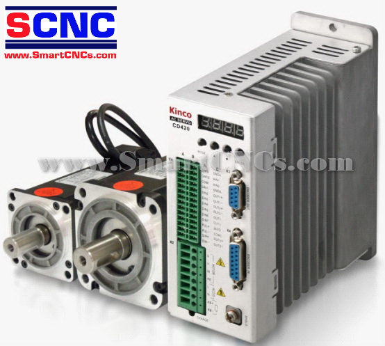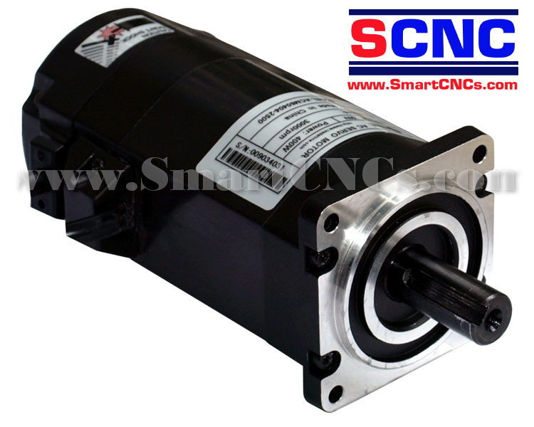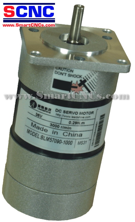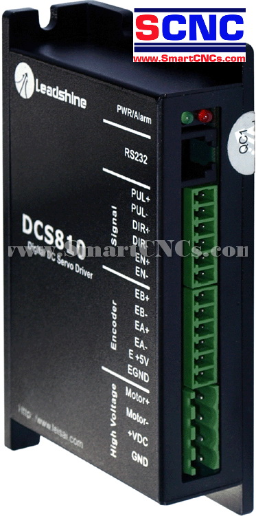

ดีซี เซอร์โว ไดรฟ์เวอร์ รุ่น DCS810 ขนาด 18-80VDC,0-20A,20-400W.
รายละเอียดสินค้า ดีซี เซอร์โว ไดรฟ์เวอร์ รุ่น DCS810 ขนาด 18-80VDC,0-20A,20-400W.
ราคายังไม่รวมภาษีมูลค่าเพิ่ม 7%
ราคายังไม่รวมค่าจัดส่ง EMS 80 บาท
Features
- 18-80VDC, 0-20A, 20-400W.
- Based on DSP control technology and high smooth servo control algorithm.
- Parameter visible tuning tools, including Pro Tuner and STU.
- Feedback resolution X4 encoder line count.
- Position Following error lock range adjustable
- Position error can be eliminated to 1 count, and Velocity error can be eliminated to the Desired Velocity* 0.3%
- Electronic gear ratio from 1/255 to 255
- Built-in motion controller for self-test with trapezoidal velocity profile
- Support PUL/DIR and CW/CCW control signals
- Opto-isolated inputs, support single-ended and differential signals
- 10 latest errors self-record function
- Over-current, over-voltage, under-voltage, phase error, encoder error, position following error protections
- Small size, surface-mount technology
Description
The DCS810 is a digital DC servo driver developed with DSP and high efficient MOSFET technologies. In position control, it's easy for the end users to change stepping drivers to the DCS810 without changing control systems, because its input command is PUL/DIR signal, which is compatible with that of stepping drivers. In low power motion control applications, performances of DC servo systems using the DCS810 are better than those of digital AC servo systems in velocity, precision, noise, stability, or at least as good as those of digital AC servo systems. However, the cost of the DCS810 stays at the price line of stepping driver, namely far lower than those of AC servo drivers.
Compared to the DCS810S, the DCS810 can accept differential control signals and differential encoder feedback signals, offering better anti-interference performances. Compared to the DB810A, parameter visible tuning tools make the DCS810 much easier to tune.
The DCS810 is very easy to tune and all parameters are visible. Parameter visible tuning tools, including Pro Tuner (Windows based setup software) and STU (Small servo tuning unit) can meet different tuning environments or requirements.


Specifications
Electrical Specifications (Tj = 25oC/77oF)
|
Parameters |
DCS810 |
|||
|
Min. |
Typical |
Max. |
Unit |
|
|
Peak output current |
0 |
- |
20 |
A |
|
Supply voltage |
+18 |
- |
+80 |
VDC |
|
Logic signal current |
7 |
10 |
15 |
mA |
|
Pulse input frequency |
0 |
- |
500 |
KHz |
|
Isolation resistance |
500 |
|
|
Mohm |
|
Current provided to encoder |
|
|
50 |
mA |
Connectors
General information
|
Control Signal Connector |
|||
|
Pin |
Signal |
Description |
I/O |
|
1 |
PUL+ |
Pulse control signal (+). See more information about PUL in 揗ore about PUL/DIR/EN Signals?section. |
I |
|
2 |
PUL- |
Pulse control signal (-). |
I |
|
3 |
DIR+ |
Direction control signal (+). See more information about DIR in "More about PUL/DIR/EN Signals" section. |
I |
|
4 |
DIR- |
Direction control signal (-). |
I |
|
5 |
EN+ |
Enable control signal (+). |
I |
|
6 |
EN- |
Enable control signal (-). |
I |
|
Encoder Signal Connector |
|||
|
Pin |
Signal |
Description |
I/O |
|
1 |
EB+ |
Encoder channel B (+) input. |
I |
|
2 |
EB- |
Encoder channel B (-) input. |
I |
|
3 |
EA+ |
Encoder channel A (+) input. |
I |
|
4 |
EA- |
Encoder channel A (-) input. |
I |
|
5 |
E +5V |
Positive pole of the auxiliary power supply (50 mA (Max)). |
O |
|
6 |
EGND |
Ground of the auxiliary power supply. |
GND |
|
Power Connector |
|||
|
Pin |
Signal |
Description |
I/O |
|
1 |
Motor+ |
Motor positive connection. |
O |
|
2 |
Motor- |
Motor negative connection. |
O |
|
3 |
+VDC |
+18 TO 80VDC power input. |
I |
|
4 |
GND |
Power ground. |
GND |
|
RS232 Communication Connector |
|||
|
Pin |
Signal |
Description |
I/O |
|
1 |
NC |
Not connected. |
- |
|
2 |
+5V |
+5V power only for STU. |
O |
|
3 |
TxD |
RS232 transmit. |
O |
|
4 |
GND |
Ground. |
GND |
|
5 |
RxD |
RS232 receive. |
I |
|
6 |
NC |
Not connected. |
- |
More about PUL/DIR/EN Signals
|
Pin Function |
Details |
|
PUL+ |
Pulse signal: In single pulse (pulse/direction) mode, this input represents pulse signal; 4-5V when PUL-HIGH, 0-0.5V when PUL-LOW. In double pulse mode (pulse/pulse) , this input represents clockwise (CW) pulse,effective at LOW level (the fixed level). For reliable response, pulse width should be longer than 1.0µs. Series connect resistors for current-limiting when using +12V or +24V control signals. |
|
PUL- |
|
|
DIR+ |
DIR signal: In single-pulse mode, this signal has low/high voltage levels, representing two directions of motor rotation(set by inside R33 and R37); in double-pulse mode, this signal is counter-clock (CCW) pulse,effective at LOW level (the fixed level). For reliable motion response, DIR signal should be ahead of PUL signal by 5µs at least. 4-5V when DIR-HIGH, 0-0.5V when DIR-LOW. Please note that motion direction is also related to motor-driver wiring and encoder feedback A/B phase signals. Exchanging the connections of two wires of the motor to the driver and A/B phase signals of encoder will reverse motion direction. |
|
DIR- |
|
|
EN+ |
Enable signal: This signal is used for enabling/disabling the driver. High level (NPN control signal, PNP and Differential control signals are on the contrary, namely Low level for enabling.) for enabling the driver and low level for disabling the driver. Usually leftUNCONNECTED (ENABLED). Series connect resistors for current-limiting when using +12V or +24V control signals. |
Typical Connections

Mechanical
Mechanical Specifications (unit: mm[inch] )