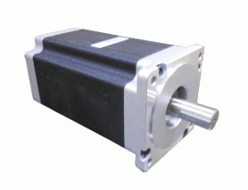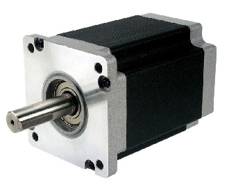

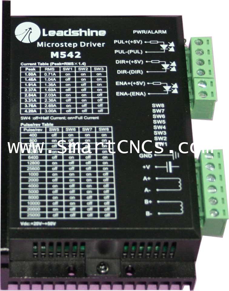
M542 ไมโครสเต็ปไดรฟ์เวอร์ ตั้งการขับกระแสได้ถึง 1A ถึง 4.2A แรงดัน 20 VDC ถึง 50 VDC
รายละเอียดสินค้า M542 ไมโครสเต็ปไดรฟ์เวอร์ ตั้งการขับกระแสได้ถึง 1A ถึง 4.2A แรงดัน 20 VDC ถึง 50 VDC
- ราคายังไม่รวมภาษีมูลค่าเพิ่ม 7%
- ราคายังไม่รวมค่าจัดส่ง EMS 80 บาทต่อตัว
-
Introduction
ไมโครเสต็ปไดรฟ์เวอร์ รุ่น M542 V2.0 เป็นเสต็ปปิ้งไดรฟ์เวอร์ คุณภาสูงที่ใช้เทคโนโลยีการควบคุมแบบ pure-sinusoidal current control ตัวไดรฟ์สามารถปรับกระแสได้อย่างเหมาะสมกับชนิดของเสต็ปมอเตอร์ทีต่ออยู่ และยังไม่ทำให้เกิดสัญญาณรบกวน (Noise) รวมถึงไม่ทำให้มอเตอร์ร้อนและทำให้การเคลื่อนที่ของเสต็ปมอเตอร์เป็นไปอย่างราบรื่นอีกด้วย อีกทั้งยังทำให้เสต็ปมอเตอร์สามารถหมุนได้ที่ความเร็วสูง ไดรฟ์ตัวนี้จึงเหมาะกับการนำไปใช้กับ เสต็ปปิ้งมอเตอร์แรงบิดสูงชนิด 2 เฟส และ 4 เฟส
Features
• High performance, cost-effective • Supply voltage up to +50 VDC • Output current up to 4.2A • Self-adjustment technology • Pure-sinusoidal current control technology • Pulse input frequency up to 300 KHz • TTL compatible and optically isolated input • Automatic idle-current reduction • 15 selectable resolutions in decimal and binary, up to 25,600 steps/rev • Suitable for 2-phase and 4-phase motors • Support PUL/DIR and CW/CCW modes • Short-voltage, over-voltage, over-current protections Applications
เหมาะสมที่จะนำไปใช้งานกับเสต็ปปิ้งมอเตอร์ขนาดต่างๆได้อย่างมากมาย ตั้งแต่ขนาด NEMA 17 ถึง NEMA 34 และตัวไดรฟ์ยังสามารถนำไปใ้ช้งานกับเครื่องจักรกลประเภทต่างๆได้เช่น X-Y tables, engraving machines, labeling machines, laser cutters, pick-place devices และอื่นๆ
Electrical Specifications (Tj = 25oC/77oC)
Parameters
M542 V2.0
Min
Typical
Max
Unit
Output current
1.0
-
4.2 (3.0 RMS)
A
Supply voltage
+20
+36
+50
VDC
Logic signal current
7
10
16
mA
Pulse input frequency
0
-
300
kHz
Isolation resistance
500
Mohm
Mechanical Specifications (unit = mm [inch])

Pin Assignment and Description
Connector P1 Configurations
Pin Function
Details
PUL+
Pulse signal: In single pulse (pulse/direction) mode, this input represents pulse signal, each rising or falling edge active (set by inside jumper J1); 4-5V when PUL-HIGH, 0-0.5V when PUL-LOW. In double pulse mode (pulse/pulse) , this input represents clockwise (CW) pulse,active at high level or low level (set by inside jumper J1, J2). For reliable response, pulse width should be longer than 1.5µs. Series connect resistors for current-limiting when +12V or +24V used. The same as DIR and ENA signals.
PUL-
DIR+
DIR signal: In single-pulse mode, this signal has low/high voltage levels, representing two directions of motor rotation; in double-pulse mode (set by inside jumper J3), this signal is counter-clock (CCW) pulse,active at high level or low level (set by inside jumper J1, J2). For reliable motion response, DIR signal should be ahead of PUL signal by 5µs at least. 4-5V when DIR-HIGH, 0-0.5V when DIR-LOW. Please note that rotation direction is also related to motor-drive wiring match. Exchanging the connection of two wires for a coil to the drive will reverse motion direction.
DIR-
ENA+
Enable signal: This signal is used for enabling/disabling the drive. High level (NPN control signal, PNP and Differential control signals are on the contrary, namely Low level for enabling.) for enabling the drive and low level for disabling the drive. Usually left UNCONNECTED (ENABLED).
ENA-
Connector P2 Configurations
Pin Function
Details
+V
Power supply, 20~50 VDC, Including voltage fluctuation and EMF voltage.
GND
Power Ground.
A+, A-
Motor Phase A
B+, B-
Motor Phase B
Selecting Microstep Resolution and drive Output Current
This drive uses an 8-bit DIP switch to set microstep resolution, and motor operating current, as shown below:
Microstep Resolution Selection
Microstep resolution is set by SW5, 6, 7, 8 of the DIP switch as shown in the following table:
MicrostepSteps/rev.(for 1.8o motor)
SW5
SW6
SW7
SW8
2
400
off
on
on
on
4
800
on
off
on
on
8
1600
off
off
on
on
16
3200
on
on
off
on
32
6400
off
on
off
on
64
12800
on
off
off
on
128
25600
off
off
off
on
5
1000
on
on
on
off
10
2000
off
on
on
off
20
4000
on
off
on
off
25
5000
off
off
on
off
40
8000
on
on
off
off
50
10000
off
on
off
off
100
20000
on
off
off
off
125
25000
off
off
off
off
Current Settings
The first three bits (SW1, 2, 3) of the DIP switch are used to set the dynamic current. Select a setting closest to your motor's required current.
Peak CurrentRMS Current
SW1
SW2
SW3
1.00A
0.71A
on
on
on
1.46A
1.04A
off
on
on
1.91A
1.36A
on
off
on
2.37A
1.69A
off
off
on
2.84A
2.03A
on
on
off
3.31A
2.36A
off
on
off
3.76A
2.69A
on
off
off
4.20A
3.00A
off
off
off
Note: ใช้ให้เหมาะสมกับค่าเหนี่ยวนำ(inductance) ของมอเตอร์แต่ละชนิดและขนาด รวมถึงค่ากระแสที่ขดลวดทำงาน โดยอาจจะมีค่าน้องกว่าค่ากระแสขณะมอเตอร์ทำงานภายไต้ภาวะการทำงานขณะหมุนที่รอบสูง
Typical Connection